
Model NO.: QB2-A
Trademark: Tianjin U-ideal Instrument
Specification: CE, ROHS, SGS, GMP
Origin: Tianjin, China
HS Code: 8481804090
Tianjin U-ideal Dual orifice Air Relief Valve;Double orifice Air vent ValvesDual orifice Air Relief Valve Features:
Ensuring huge amount of air relief while filling pipeline with water,
Providing huge amount of air entrance while pipeline discharging,
Releasing bubbles that comes with fluid dynamic operation conditions,
Protection against self-locking by huge amount of air relief,
Kinetic type with single ball, dynamic type with single ball, combined with dual orifice type, and dual ball self-valve are types of air relief valves depending on their place of use.
Applications for Tianjin U-ideal float-type air vents include hydronic heating systems, water service lines, water storage tanks, centrifugal pumps, gas lines, solvent filters and similar equipment. Operation is completely automatic, and the simple design and quality mechanism make operation trouble-free and maintenance infrequent.
Air vent valves are used to allow the pressure in the tank to balance while preventing the spillage of the fluid through the vent lines. These valves allow the free flow of fluid or air in or out of a chamber or tank until they close, usually activated by a float.
During refueling, incoming fuel dis-places the air in the tank. The vent valve allows this air to escape through a designated vent path
When the tank is full, the float valve closes preventing the fuel from escaping. These valves also allow air to re-enter the tank as fuel is consumed, preventing dangerous negative pressure and potential fuel starvation. Vent valves protect the fuel tank from pressure damage resulting from expansion and contraction of the fuel due to changes in temperature. In some applications they incorporate measures to prevent the fuel from exiting the tank when the aircraft is inverted either during flight or in an emergency.
Why remove air from a water system?
Every building services engineer knows that air trapped in either a hot or chilled water system can cause
trouble, such as excessive noise, corrosion and increased maintenance costs. Air can cause air locks which inhibit the filling of the system or the priming of pumps. It can seriously affect the accuracy of flow measurement meters and regulating valves. Under extreme conditions it may even temporarily decommission plant. Air and other incondensable gases considerably reduce heat transfer efficiency. A film of air 1 mm thick presents the same barrier to heat transfer as a wall of copper 13 m thick!
Entrapped air in any water system is a threat to thermal efficiency. It is particularly damaging in a chilled water system which does not have the natural deaerating ability of hot water.
Air Valves vs. HydrantsÂ
There is a common misconception that fire hydrants can be used in place of combination air valves to provide the required air-release service. This method should be strongly discouraged for several reasons:Â
The use of fire hydrants requires active user intervention, which creates a hidden maintenance cost. In order to be effective, the hydrants should be discharged once per day. At just five minutes per hydrant at a rate of $10.00 per hour, a small town with twenty hydrants would spend more on the labor used than it would have spent on twenty automatic air valves.Â
Manual air release cannot accommodate surges in flow or demand. Only automatic air valves can provide the needed functions on demand in order to protect the water system.Â
Hydrants cannot provide the vacuum-breaking function required to prevent contamination during negative-pressure events. Automatic air valves help protect the finished water at all hours, every day of the year.Â
The pressures accumulated within the hydrant, even at a system pressure of 80 psi, can be extremely hazardous to maintenance workers. Accumulated pressures in some systems can reach more than ten times the rated system water pressure. Automatic air valves work without user intervention and prevent the accumulation of pressure.Â
Hydrants are typically mounted to the sides of a main (at the 3 o'clock and 9 o'clock positions), rather than at the top. This can significantly reduce their effectiveness as air-release devices, even when flanged at the full diameter of the main. Automatic air valves are properly installed only at the top (12 o'clock) position, where they can provide complete discharge of accumulated air.Â
Combination air valves from Tianjin U-ideal are the most advanced sold anywhere in the world.Contact us for custom specifications and calculations by send e-mail, and we'll be happy to share more about them with you.Â
Â
| Origin | Tianjin China |
| Brand | Tianjin U-ideal Instrument |
| Connection | Flange or thread |
| Export Markets | Global |
| Packing | Wooden Case or Carton |
| About us | Our company is specialized in the manufacture of valves, ,flow meters,level gauges,etc |
| Why Choose us | |
| Rich experience | We have been engaged in machining for many years. Our company had good reputation with customers from American, Europe, North America, and Australia, India etc. We also have a good team for sale and quality control. |
| Good service | We will respond to you within 24 hours. We manufacture non-standard parts according to your drawings. And we will continue to serve you after sales and will be responsible for the mistakes from us. |
| Low price | The prices of our production are reasonable! The prices will be much better if your quantity is good. |
| Perfect quality | We have strict quality control from producing to delivery. Our company had strong technology support, 80% of our colleagues are master or bachelor's degree. We have cultivated a group of managers who are familiar with product quality, good at modern concept of management. |
| Contact | |
| If you have any question or requirements, please don't hesitate to contact us. Tel: 86-22 88971536 Fax: 86-22 88971536 | |
Â
DIN 2631 Pn6 Welding Neck Flange
|
Germany standard flange DIN 2631 welding neck flanges; nominal pressure 6
|
||||||||||||||||
|
Vorschweißflansche DIN 2631 Nenndruck 6
|
||||||||||||||||
|
Brides à souder à collerette DIN 2631: pression nominale 6
|
||||||||||||||||
| Pipe | Flange | Neck | Raised face | Screws | Weight | |||||||||||
| (7,85 Kg/dm3) | ||||||||||||||||
| Rated | d1 | D | b | k | h1 | d3 | s | r | h2 | d4 | f | Holes | Thread | d2 | Kg | |
| Diameter | ISO Series | DIN Series | ||||||||||||||
| 15 | - | 20 | 80 | 12 | 55 | 30 | 28 | 2 | 4 | 6 | 40 | 2 | 4 | M 10 | 11 | 0,392 |
| 21,3 | - | 30 | ||||||||||||||
| 20 | - | 25 | 90 | 14 | 65 | 32 | 35 | 2,3 | 4 | 6 | 50 | 2 | 4 | M 10 | 11 | 0,592 |
| 26,9 | - | 38 | ||||||||||||||
| 25 | - | 30 | 100 | 14 | 75 | 35 | 40 | 2,6 | 4 | 6 | 60 | 2 | 4 | M 10 | 11 | 0,747 |
| 33,7 | - | 42 | ||||||||||||||
| 32 | - | 38 | 120 | 14 | 90 | 35 | 50 | 2,6 | 6 | 6 | 70 | 2 | 4 | M 12 | 14 | 1,05 |
| 42,4 | - | 55 | ||||||||||||||
| 40 | - | 44,5 | 130 | 14 | 100 | 38 | 58 | 2,6 | 6 | 7 | 80 | 3 | 4 | M 12 | 14 | 1,18 |
| 48,3 | - | 62 | ||||||||||||||
| 50 | - | 57 | 140 | 14 | 110 | 38 | 70 | 2,9 | 6 | 8 | 90 | 3 | 4 | M 12 | 14 | 1,34 |
| 60,3 | - | 74 | ||||||||||||||
| 65 | 76,1 | - | 160 | 14 | 130 | 38 | 88 | 2,9 | 6 | 9 | 110 | 3 | 4 | M 12 | 14 | 1,67 |
| 80 | 88,9 | - | 190 | 16 | 150 | 42 | 102 | 3,2 | 8 | 10 | 128 | 3 | 4 | M 16 | 18 | 2,71 |
| 100 | - | 108 | 210 | 16 | 170 | 45 | 122 | 3,6 | 8 | 10 | 148 | 3 | 4 | M 16 | 18 | 3,24 |
| 114,3 | 130 | |||||||||||||||
| 125 | - | 133 | 240 | 18 | 200 | 48 | 148 | 4 | 8 | 10 | 178 | 3 | 8 | M 16 | 18 | 4,49 |
| 139,7 | - | 155 | ||||||||||||||
| 150 | - | 159 | 265 | 18 | 225 | 48 | 172 | 4,5 | 10 | 12 | 202 | 3 | 8 | M 16 | 18 | 5,15 |
| 168,3 | - | 184 | ||||||||||||||
| 200 | 219,1 | - | 320 | 20 | 280 | 55 | 236 | 5,9 | 10 | 15 | 258 | 3 | 8 | M 16 | 18 | 7,78 |
| 250 | - | 267 | 375 | 22 | 335 | 60 | 282 | 6,3 | 12 | 15 | 312 | 3 | 12 | M 16 | 18 | 10,8 |
| 273 | - | 290 | ||||||||||||||
| 300 | 323,9 | - | 440 | 22 | 395 | 62 | 342 | 7,1 | 15 | 15 | 365 | 4 | 12 | M 20 | 22 | 14 |
| 350 | 355,6 | - | 490 | 22 | 445 | 62 | 385 | 7,1 | 12 | 15 | 415 | 4 | 12 | M 20 | 22 | 18,5 |
| - | 368 | 16,7 | ||||||||||||||
| 400 | 406,4 | - | 540 | 22 | 495 | 65 | 438 | 7,1 | 12 | 15 | 465 | 4 | 16 | M 20 | 22 | 21,2 |
| - | 419 | 19 | ||||||||||||||
| 500 | 508 | - | 645 | 24 | 600 | 68 | 538 | 7,1 | 12 | 15 | 570 | 4 | 20 | M 20 | 22 | 28,6 |
| 600 | 610 | - | 755 | 24 | 705 | 70 | 640 | 7,1 | 12 | 16 | 670 | 5 | 20 | M 24 | 26 | 31,5 |
| 700 | 711 | - | 860 | 24 | 810 | 70 | 740 | 7,1 | 12 | 16 | 775 | 5 | 24 | M 24 | 26 | 37,4 |
| 800 | 813 | - | 975 | 24 | 920 | 70 | 842 | 7,1 | 12 | 16 | 880 | 5 | 24 | M 27 | 30 | 46,1 |
| 900 | 914 | - | 1075 | 26 | 1020 | 70 | 942 | 7,1 | 12 | 16 | 980 | 5 | 24 | M 27 | 30 | 55,6 |
| 1000 | 1016 | - | 1175 | 26 | 1120 | 70 | 1045 | 7,1 | 16 | 16 | 1080 | 5 | 28 | M 27 | 30 | 61,9 |
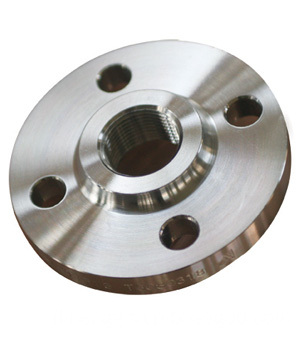
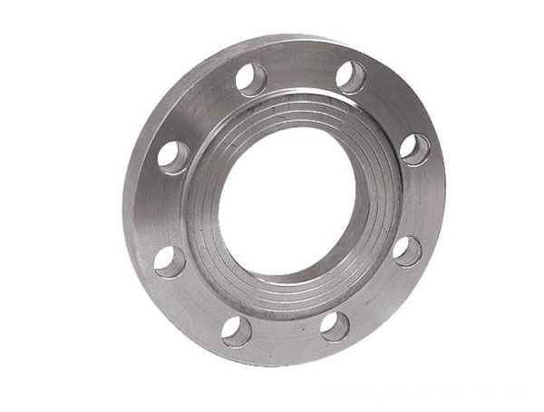
DIN 2631 Pn6 Welding Neck Flange
DIN 2631 Pn6 Welding Neck Flange, Pn6 Flange, Welding Neck Flange
Hebei Jimeng Highstrength Flange-tubes Group Co.,Ltd. , https://www.jimengflange.com