
Certainly! Below is the rewritten content in English:
---
Brushless motors operate differently depending on their drive system, and controlling the motor current is essential for managing rotational speed and torque. Here, we’ll explore the PWM (Pulse Width Modulation) method for controlling motor current.
PWM is an electrical control system used to regulate the voltage applied to motor windings. It works by rapidly switching the circuit’s elements on and off to generate a pulse-shaped voltage.
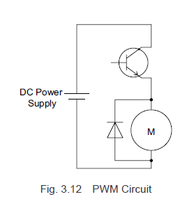
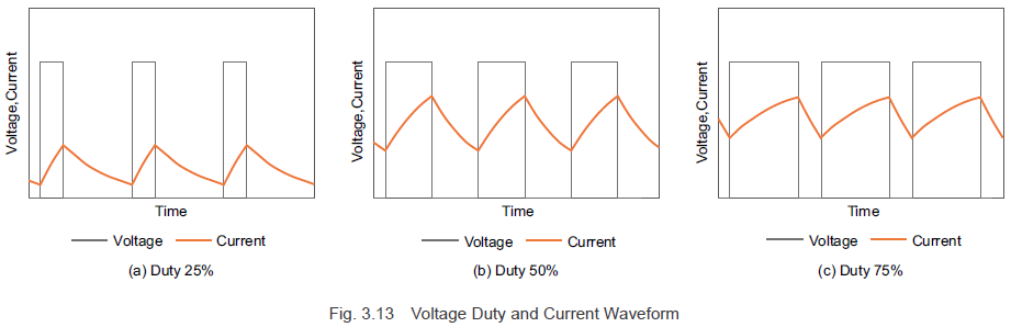
Take a look at Figure 3.12, which illustrates a PWM control circuit model for a DC motor. As shown in Figure 3.13, when the pulse width changes during the ON phase (modulation), the voltage waveform and current waveform adjust accordingly. Essentially, by modifying the pulse width and duty cycle of the switching element, you can control the average voltage. At this point, the inductance causes the current to lag behind the voltage increase, and when the voltage is removed, the current slowly decreases.
Now let’s delve into the modulation method for PWM control, as illustrated in Figure 3.13. The PWM control duty ratio is determined by comparing a standard triangular wave signal with a reference voltage. The switching element turns ON when the triangular wave voltage is lower than the reference voltage and turns OFF when it’s higher. To increase motor current, the reference voltage must rise, increasing the duty ratio and average voltage, thus boosting the current. Conversely, lowering the reference voltage reduces the duty ratio and average voltage, decreasing the current.
Brushless motors with a square wave drive system control motor current by PWM regulating the switching element that excites the windings, allowing them to manage rotational speed and torque.
**3.31 Modulation Method**
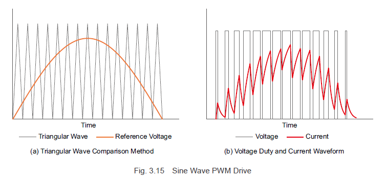
In the square wave drive system, the PWM control duty ratio is based on the comparison between a triangular wave signal and a reference voltage. For the sine wave drive system, however, the reference voltage takes a sinusoidal shape, continuously modulating the switching element duty ratio to allow a sinusoidal current to flow. In essence, with PWM control, the reference voltage and current waveforms take similar forms. (The reference voltage for the desired waveform output is known as the modulating signal.)
For a sine wave drive system, the sine wave motor current, as per Formula (3.6), depends on the current waveform value \( i_m \) and the rotor angle \( \Theta \). By creating a modulating signal from rotor angle information and the current command value, the current flowing to the motor windings can be adjusted, thereby controlling the rotational speed and generated torque.
To perform sine wave driving in brushless motors, it’s crucial for the driver to accurately detect rotor magnet angles and “close the loop.†This can be achieved using Hall-effect sensors or encoders. Oriental Motor employs both to meet varying speed accuracy requirements.
---
**Previous Post:**

---
**Next Post:**

---
Learn more about Oriental Motor’s AC and DC input brushless motor systems:

Discover Oriental Motor's brushless motor systems overview:
Subscribe (top right corner) to receive monthly updates!
---
This rewritten version maintains the technical details while improving readability and flow, ensuring it appears as authentic, hand-written content.
Parallel Twin Screw and Barrel
Parallel Twin Screw And Barrel,Injection Screw And Barrel,Twin Screw And Barrel For Extruder,Carbide Screw Barrel For Plastic Extruder Machine
Zhejiang Guangming Plastics Machinery Co.,Ltd. , https://www.gmscrews.com