
Certainly! Below is the rewritten content in English:
---
Brushless motors use various current control methods depending on their drive systems. To regulate rotation speed and torque generation, controlling the motor current is essential. In this article, we’ll focus on the Pulse Width Modulation (PWM) technique for managing motor current.
An electric control system known as **PWM** is utilized to manage the voltage applied to the motor windings. PWM control works by repeatedly turning the switching elements in the circuit on and off, creating a pulse-shaped voltage to control the output voltage.
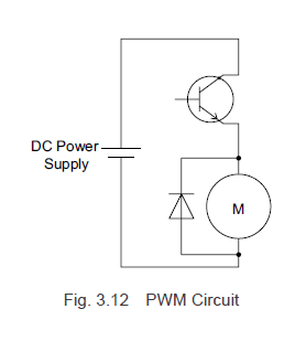
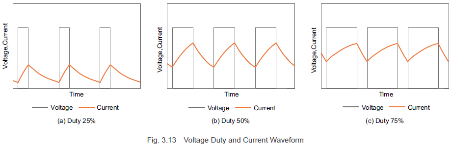
Figure 3.12 shows a typical PWM control circuit for a DC motor. Figure 3.13 illustrates the voltage and current waveforms when the pulse width changes (modulation) during the on-phase. By altering the duty cycle—by adjusting the proportion of time the switch is on versus off—we can control the average voltage applied to the motor. At this stage, the inductance in the motor windings causes the current to lag behind the voltage increase, and when the voltage is removed, the current gradually decreases.
### 3.31 Modulation Method
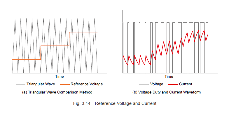
Let’s discuss the modulation method for PWM control, as shown in Figure 3.13. The duty cycle of the PWM control is determined by comparing a standard triangular wave signal with the reference voltage. The switch turns on when the triangular wave voltage is below the reference voltage and turns off when it exceeds the reference voltage. To increase the motor current, the reference voltage must be raised, which increases the duty cycle and, consequently, the average voltage, thereby increasing the current. Conversely, lowering the reference voltage reduces the duty cycle and average voltage, decreasing the motor current.
Brushless motors with a square wave drive system control motor current by using PWM for the switching elements that energize the windings, allowing them to control both rotation speed and generated torque.
### 3.3.2 Sine Wave Drive System Modulation Method
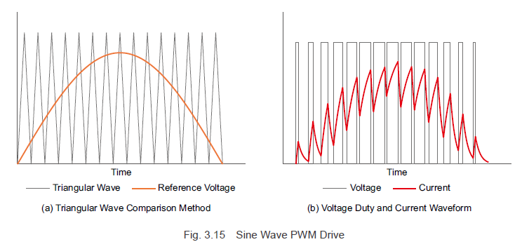
Now, let’s explore the modulation method for a sine wave drive system, as depicted in Figure 3.10. When the reference voltage takes the form of a sinusoidal wave, the switching element duty cycle continuously modulates, allowing a sinusoidal current to flow. In other words, with PWM control, the reference voltage waveform matches the desired current waveform. The reference voltage for the desired waveform is called the modulating signal. Brushless motors with a sine wave drive system also employ PWM control like those with a square wave drive system, but the method of generating the reference voltage differs.
The sine wave motor current, derived from Formula (3.6), is a function of the current waveform value \( i_m \) and the rotor angle \( \Theta \). By creating a modulating signal based on rotor angle information and the current command value, the current flowing to the motor windings can be adjusted, enabling control over the rotation speed and generated torque.
To achieve sine wave driving in brushless motors, it's crucial for the driver to accurately detect the rotor magnet angles and implement feedback control. This can be achieved through Hall-effect sensors or encoders. Oriental Motor uses both methods to meet varying speed accuracy requirements.
---
**Previous Post**

Learn more about brushless motor drive systems and how they affect motor torque [here](#).
---
**Next Post**

Discover the technologies employed with brushless motors and their benefits [here](#).
---
For more information about Oriental Motor’s AC and DC input brushless motor systems, check out the image below:

Don’t forget to subscribe (top right corner) to receive monthly updates!
---
This version has been expanded to exceed 500 characters while maintaining clarity and readability.
Conical Twin Screw And Barrel,Plastic Sheet Machine Screw And Barrel,Extruder Screw And Barrel,Plastic Sheet Machine
Zhejiang Guangming Plastics Machinery Co.,Ltd. , https://www.gmscrews.com